Overview
This product is recommended for ongoing projects only. New designs should consider using the Diamond-MM-32DX-AT
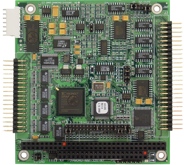
DMM-32X-AT is an advanced embedded A/D board. It includes a comprehensive suite of analog and digital features to fit a wide variety of embedded application needs
Industry-Leading Auto-Autocalibration Provides Maximum Accuracy
DMM-32X-AT includes Diamond Systems’ patented auto-autocalibration technology. This circuitry enables automatic calibration of the board in response to changes in temperature without requiring any involvement by the user or application program. An on-board microcontroller monitors the board’s temperature and uses on-board calibration circuitry to bring the board into calibration whenever needed, totally automatically. Typical accuracy post-calibration is +/-1LSB. The calibration threshold is set for 5 degrees C, which typically limits measurement errors to only +/-2 to +/-3LSB pre-calibration. Click here to learn more about this advanced technology patented by Diamond Systems.
Low-drift circuitry: The reference voltage is the foundation of any A/D board’s accuracy. On DMM-32X-AT, a precision low-drift analog voltage reference chip is used as the basis for the A/D circuit. This low-drift device limits natural measurement errors induced by changes in the ambient temperature of the system.
Auto-Autocalibration: All A/D circuits require occasional calibration to maintain their accuracy. The need is even greater when dealing with wide temperature ranges, since temperature is the largest contributor to analog circuit drift. The auto-autocalibration feature on DMM-32X-AT maintains measurement accuracy to within +/-1LSB typical across its entire operating temperature range. Auto-autocalibration is completely automatic and requires no user input. Click here to learn more about this advanced technology patented by Diamond Systems.
Low noise design: A 16-bit A/D converter measures signals down to the level of tens of microvolts. This extreme sensitivity can be easily swamped by noise from nearby high-speed, high-power digital circuitry such as the CPU. On DMM-32X-AT, careful attention is paid to component placement and trace layout in order to minimize noise in the analog circuitry. Digital and analog circuits are kept separate on the board and are placed over their respective power and ground plane, which are also separated. Digital signals that cross over into the analog region pass through isolating resistors at the transition point to further minimize digital noise effects. In addition, components with high power supply rejection ratio specifications are used in the design to further enhance immunity to power supply noise. This results in low-noise, reliable analog readings for all input voltage ranges.
High bandwidth: The maximum sampling rate of an A/D board is often only achievable when sampling a single channel. Limited bandwidth in the analog input circuit can produce significant errors when conducting high speed sampling across multiple channels, because the input circuit cannot settle on the new input voltage in time to present an accurate signal to the A/D converter. On DMM-32X-AT, this issue has been specifically addressed and tested. The analog circuit bandwidth supports accurate full-speed sampling for a single channel or any number of channels, in all configurations and all input ranges.